- Out-of-Stock


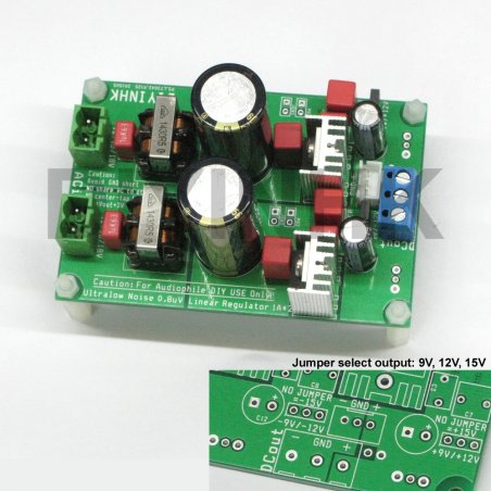
This item includes PCB with Linear Technology newest 0.8uV ultralow noise regulator LT3042
*All SMT component are soldered, thru-hole component are not soldered.
This is the best ultralow noise power supply regulator for Diyer to enjoy, use of decade old 78xx / lm3xx /lt10xx is simply kidding for audiophiles.
This regulator PCB equiped with high quality hybrid choke coil and CRC input filter to remove the common mode noise and differential mode noise from the input and provide the best sound result from time to time.
It is always a mystery for most people why the same DAC usually sound better at night. The reason is the noise pollution through the AC line from all the other equipment in the same room. In the day time, More electronic equipment turn on and there are more pollution.
Feature:
1)Linear Technology 0.8uV ultralow noise LT3042 regulator
2) +-9V/12V/15V 1.5A* output switchable with a jumper easily. Please notes 1.5A is the burst value, please read the bottom notes for output usage larger than 0.5A continuously.
3)Panasonic EEUFC low ESR 5600uF capacitor and the red WIMA film capacitor are sourced from authorized distributor Arrow Electronics directly (guarantee no fake product from China)
4)The PCB follows the official demo circuit for ultimate performance.
5) Compact size 60mm x 90mm
Assembly Instruction:
1) Double check the polarity of the 5600uF capacitor is correct before connect AC power input to the PCB, the capacitor will explode immediately if it is reversed connected. No return is accepted after the pcb is soldered.
2) Cut JP1 on the bottom side and the PCB can be use as two individual rail.
Attention***
1) According to the LT3042 official datasheet the maximum input voltage is 20V. Therefore, extra care should be taken when choosing the transformer, there are some transformer on the market labelled as 18V output but the output can be as high as 28V! when the loading is low. The LT3042 chip will be damaged immediately if the voltage is larger than the input maximum limit. The measured DC voltage at the large capacitor must lower then 20V all the time during any low and high loading current output condition. (Please notes the labelled AC output voltage value is not the voltage of most transformer during no loading, user can measure the AC RMS value output from the transformer, multiple it by 1.414 and minus 1. It is the DC voltage after the full bridge rectifier(there is about 1V voltage drop in the full bridge rectifier diode)
2) Don't remove the voltage switch jumper when the pcb is using. The output voltage will jump to maximum 15V.
This item is in limited stock, maximum 2pcs per buyer. Please contact us if you want to buy more than 2, thanks.
Notes for advance user:
For linear regulator, all unused voltage is converted to heat, if the PCB is used for output larger than 0.5A current continuously, depends on the room temperture, larger heatsink and fan is needed. The same usage method is applied to all linear regulator in the market. The operating temperature should always keep below the rated maximum operating temperature as listed in the manufacturer official datasheet.
The murata EMI filter used in the PCB is rated 0.5A at 60degrees celsius from the manufacturer. As most modern DAC uses less than 0.5A per rail, we choose the highest inductance in the series. The filter can actually deliver larger than 0.5A if it can keep below 60degree. The PCB can also delivery larger than 1A if the temperature can keep low. The theoretical maximum is calculated from the current boost transistor combined with the 4.7ohm base emitter resistor, it can burst upto 15A output current!
As the PCB can actually output higher than 1A, the first overheat component will be the input choke, the second is the full bridge diode rectifier. The transistor is rated at maximum 15A, the LT3042 has internal current limit and overheat protection will survive.
If the operating temperature is too high, user should bypass or replace the EMI filter with lower inductance in the series which generate less heat but the drawback is less noise filtered.
Data sheet
You might also like